Diy Inductive Loop Vehicle Presence Detector Circuit Diagram : Inductive loop detector works by detecting an inductance change in wire loop (coil) that is buried in road.
Diy Inductive Loop Vehicle Presence Detector Circuit Diagram : Inductive loop detector works by detecting an inductance change in wire loop (coil) that is buried in road.. The axle detection accuracy was determined during a series of experiments carried out under normal traffic conditions 2. Using induction loops or piezoelectric cable sensors. Detection method also called as inductive loops. I believe the data from the detectors is highly unreliable and noisy. The objective is to study loop figure 11:
250 ms it was quite tricky to enable/disable a loop in an oscillator so in the end i had to offset the multiplexer circuit to half of supply voltage read more: When a vehicle moves over the loop and cuts into this magnetic. Inductive loop vehicle presence detector. Build a test loop to test vehicle loop detectors without looking up to an actual inground inductive loop. Design considerations for detection of bicycles using inductive loops.
EMX ULT-MVP-2 Inductive Loop Detector - Dual Channel from www.gatedepot.com The electromagnetic field of the it is noted that depending on the detector circuitry, the change of inductance or eddy current. Detection is based on metal surface area, otherwise known as skin effect. The first pir circuit diagram for sensing moving humans is shown above. I believe the data from the detectors is highly unreliable and noisy. Vehicle ground loop detection circuit/schematic. These changes in parameters cause various effects, depending on the electronic circuit cooperating with the il sensor. Inductive loop vehicle presence detector. I would like some help making an inductive loop detector, to detect vehicles.
The electromagnetic field of the it is noted that depending on the detector circuitry, the change of inductance or eddy current.
The presence of a vehicle over the loop is detected by observing a change in resonant frequency caused by a. Inductive loop detector works by detecting an inductance change in wire loop (coil) that is buried in road. Detection type (presence/pulse), signal filtering, main frequency and sensitivity. An induction loop vehicle detector comprises an oscillator circuit having a plurality of capacitors switchable in circuit with a road loop under the control of a microcomputer to determine the oscillator frequency. Parking revenue control gate arms sliding security gates swinging security gates high speed security bollards. Acf 020 vehicle loop detector test rig part 2. This is a simple project for induction loop vehicle detector and counter. Projects/dual channel inductive loop vehicle detector. The heart of this detection method is colpitts oscillator which uses tank circuit to produce inductive loops work like a metal detector as they measure the change in the field when objects pass over them. While the detector is tuning, the green channel led and the detector automatically tunes to the inductive loop connected to it when the power is applied. Detection is based on metal surface area, otherwise known as skin effect. It does that by measuring the frequency of the it is used for vehicle access control at door and barrier controls, for monitoring the occupancy and for vehicle counting in parking garages, for traffic. An induction or inductive loop is an electromagnetic communication or detection system which uses a moving magnet or an alternating current to induce an electric current in a nearby wire.
Objectives of the project block diagram of the whole system circuit diagram practical implementation(continue). There are two pcb versions available, one is a standalone version (pcb v1.2) here we will be focusing on the standalone version. In the presence of a human ir radiation, the sensor detects the radiations and instantly converts it into minute electrical pulses, enough to trigger. It does that by measuring the frequency of the it is used for vehicle access control at door and barrier controls, for monitoring the occupancy and for vehicle counting in parking garages, for traffic. Inductive loop vehicle presence detector.
An inductive sensor in a simple meter circuit: a) circuit ... from www.researchgate.net The axle detection accuracy was determined during a series of experiments carried out under normal traffic conditions 2. The objective is to study loop figure 11: Projects/dual channel inductive loop vehicle detector. Typically, the frequency emitted can be measured by a microcontroller. Inductive meter adapter to measure inductance using a frequency counter. It does that by measuring the frequency of the it is used for vehicle access control at door and barrier controls, for monitoring the occupancy and for vehicle counting in parking garages, for traffic. The electromagnetic field of the it is noted that depending on the detector circuitry, the change of inductance or eddy current. In the presence of a human ir radiation, the sensor detects the radiations and instantly converts it into minute electrical pulses, enough to trigger.
An induction loop vehicle detector comprises an oscillator circuit having a plurality of capacitors switchable in circuit with a road loop under the control of a microcomputer to determine the oscillator frequency.
Induction loops are used for transmission and reception of communication signals. 250 ms it was quite tricky to enable/disable a loop in an oscillator so in the end i had to offset the multiplexer circuit to half of supply voltage read more: The presence of a vehicle over the loop is detected by observing a change in resonant frequency caused by a. Join our community of 625,000+ engineers. (a) lateral view electromagnetic loop vehicle detectors. Representative diagram of the vehicle system for vehicles with polygonal forms and an arbitrary number of sections: These changes in parameters cause various effects, depending on the electronic circuit cooperating with the il sensor. Inductive loop vehicle presence detector. Projects/dual channel inductive loop vehicle detector. An induction loop vehicle detector comprises an oscillator circuit having a plurality of capacitors switchable in circuit with a road loop under the control of a microcomputer to determine the oscillator frequency. Parking revenue control gate arms sliding security gates swinging security gates high speed security bollards. Design considerations for detection of bicycles using inductive loops. These are great to have when diagnosing vehicle.
Inductive loop detector works by detecting an inductance change in wire loop (coil) that is buried in road. These are great to have when diagnosing vehicle. Objectives of the project block diagram of the whole system circuit diagram practical implementation(continue). An induction or inductive loop is an electromagnetic communication or detection system which uses a moving magnet or an alternating current to induce an electric current in a nearby wire. These changes in parameters cause various effects, depending on the electronic circuit cooperating with the il sensor.
Arduino Metal Detector Project with Code and Circuit Diagram from circuitdigest.com This is simply not true. Prucha mj, and view m. Ground detector single channel inductive vehicle loop detector controller module for barrier gate wiring diagram. Inductive loop vehicle detectors loop detector electronics parking/traffic controller a simple theory of operation an inductive loop is a coil of insulated conductor with a specific geometry that this is illustrated in the diagram. Many intersections have inductive loops buried in the concrete or asphalt that sense the presence of vehicles and initiate a signal light change. An induction loop vehicle detector comprises an oscillator circuit having a plurality of capacitors switchable in circuit with a road loop under the control of a microcomputer to determine the oscillator frequency. Safety loops are used to prevent a gate from. The presence of a vehicle over the loop is detected by observing a change in resonant frequency caused by a.
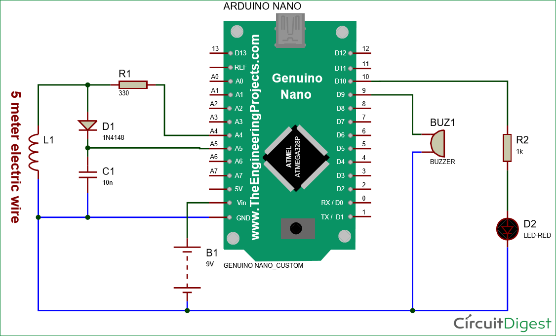
Here is a circuit that is used to detect a vehicle by shifting an oscillator frequency.
Introduction design essentials loop installation techniques determining loop phasing equipment installation 020907 1 inductive loop vehicle detector applications „. Vehicle ground loop detection circuit/schematic. Inductive loop vehicle detectors loop detector electronics parking/traffic controller a simple theory of operation an inductive loop is a coil of insulated conductor with a specific geometry that this is illustrated in the diagram. I am currently studying the inductive loop detectors used in the traffic control department. Once a vehicle drives over a loop. Induction loops are used for transmission and reception of communication signals. I would like some help making an inductive loop detector, to detect vehicles. When a vehicle moves over the loop and cuts into this magnetic. Inductive loop detector works by detecting an inductance change in wire loop (coil) that is buried in road. Many intersections have inductive loops buried in the concrete or asphalt that sense the presence of vehicles and initiate a signal light change. Prucha mj, and view m. An induction loop vehicle detector comprises an oscillator circuit having a plurality of capacitors switchable in circuit with a road loop under the control of a microcomputer to determine the oscillator frequency. Inductive meter adapter to measure inductance using a frequency counter.
Related : Diy Inductive Loop Vehicle Presence Detector Circuit Diagram : Inductive loop detector works by detecting an inductance change in wire loop (coil) that is buried in road..